neutral grounding resistors
Long Service Life
Warranty and Technical Support
Fast Delivery
International Certifications
neutral grounding resistors
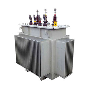
Neutral Grounding Resistors (NGRs) are used to limit fault currents and ensure the safety of both equipment and personnel in industrial systems. Installed between the neutral point and ground, NGRs increase the total resistance during a ground fault, keeping the phase-to-ground fault current at a safe level.
The advantages of NGRs are as follows:
Reducing single-phase fault currents in medium-voltage networks to levels that will not damage equipment
Limiting overvoltages occurring during a ground fault and ensuring the operation of the ground fault relay
Protecting generators, transformers, and other equipment
Extending the service life of switching devices
Reducing operation and maintenance costs
Increasing the insulation level of certain equipment with low insulation capacity
Reducing step voltage
The fault current value must be limited according to the level that transformers and other equipment can withstand. In addition, the fault current must be high enough to be detected by ground fault relays. If the resistance value of the NGR is too high, the fault current becomes too low and may not be detected by ground fault relays.
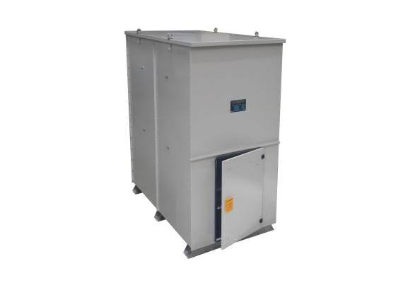
General Features
Stainless steel resistor elements
Built-in current transformer (EN 61869-2)
Bolted resistor element connections instead of welded connections, allowing immediate installation of spare parts on site
Hot-dip galvanized sheet metal enclosure (painted and stainless steel enclosure available on request)
Stainless steel lifting lugs for safe transportation
Robust structure against shock impacts (IK10)
Sloped and high-strength roof preventing water accumulation
Corrosion-resistant stainless steel nameplate
Exproof (ATEX) certified design available on request
Technical Specifications
Operating Voltage: Systems up to 110 kV phase-to-phase
Rated Current: Up to 5000 A
Ambient Temperature: Up to 55°C (please inquire for higher temperatures)
Resistor Material: Stainless steel (CrNi or CrAl)
Protection Class: IP 23 (outdoor) and others on request
Standards: IEEE C57.32, IEC 60076-25, IEC 60137 & 60273, EN ISO 1461, EN 10346, EN ISO 12944, IEC 60071, IEC 60060, IEC 60529
Resistors are also categorized according to the duration for which they can withstand fault current. This duration is generally between 5 and 10 seconds. In industries such as oil, mining, and similar sectors, continuity of supply is extremely important, so longer withstand durations are required. In such applications, selecting resistors with higher resistive values is recommended.
When a ground fault occurs, an alarm related to the fault is generated in the system. However, the goal is for the system to continue operating until the next planned shutdown.
Hilkar Neutral Grounding Resistors meet the requirements for absorbing high amounts of energy without exceeding the temperature limit values specified in IEEE 32 standards. Neutral Grounding Resistors can be manufactured for indoor or outdoor environmental conditions.
The neutral point connection can be made by porcelain bushing or high-voltage XLPE cable, and according to customer request it can generally be connected from the bottom, top, or side using a minimum of 70 mm² copper or 95 mm² aluminum cable.
The most commonly preferred protection class for Neutral Grounding Resistors is IP 23, due to the cooling advantages it provides. Since all resistor elements are manufactured from stainless steel, they are minimally affected by harsh conditions such as humidity, dust (coastal areas, deserts, etc.).
Neutral Grounding Resistors are supplied together with installation and maintenance manuals, and the most suitable relay settings for each neutral grounding resistor are also provided to the user. In Hilkar Neutral Grounding Resistor applications, suitable options are offered to customers depending on technical support and site conditions.
Routine Tests
Power frequency withstand test (applied voltage test)
DC resistance test
Block insulation test
Measurement of coating thickness (paint and/or galvanization)
Type Tests
Temperature rise test
Protection degree test
Impulse withstand voltage test (1.2 / 50 µs)
Special Tests (on request)
AC resistance measurement
Seismic withstand test
Insulation resistance measurement (Megger)
Ordering Information
System voltage (kV)
Phase-to-neutral voltage (kV)
Current (A)
Resistance (Ohm)
Operating time (seconds) and duty cycle
Bushing or cable entry
Current transformer ratio (if a special ratio is requested)
Disconnector (if any)
Special additions
Selecting the Appropriate NGR
Although the selection of a neutral grounding resistor depends on several complex parameters (line capacitance, line length, etc.), in practice the NOMINAL CURRENT of the generator and transformer whose current is to be limited can be taken as the basis. For example, for the neutral of a transformer with a nominal current of 550 A, a 500 A 10-second NGR is sufficient.
NGR Options
Additional legs to raise the unit from the ground
Explosion-protected, ATEX-certified solutions
Specially designed resistors and enclosures for harsh climatic conditions
Addition of voltage transformer
Addition of protection relays
Top- or side-mounted porcelain entry bushings (boxed if required)
Grounding transformer
Motorized / non-motorized single-pole disconnector or single-pole breaker, surge arrester, panel heater additions
Plug-in bushing entry option